09/05/2019
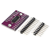
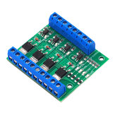
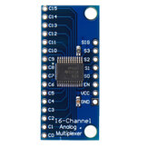
This is a great interface for the multiplexer chip, and very easy to use. Basically, it is a 1-to-8 or a 8-to-1. It works both ways! Essentially, you apply true/false to the S0, S1, and S2 inputs in the combination of a binary number to indicate which of the Y pins you want connected to the Z pin. Then it acts as though it has physically connected the two pins, and only those two pins, together. Power goes both ways.
Simplest application: Connect each Y pin to an LED, then an appropriate resistor (440Ohm) and then to ground. Connect the Z pin to Vcc (5V). Connect the VCC to 5V and GND to ground. Connect E to ground to enable the board (high will disable it.) Then connect each of the S pins to either VCC or GND in different combinations. For each combination, a different LED will be lit.
This component is best used when you have 8 outputs that can be activated one at a time, but only have 4 or 5 pins for your output.
If you combine two of these boards, you can use the E pin as a fourth addressing bit, turning 5 pin outputs into 16.